
LTspice has various options to generate a custom pulse for circuit simulations.
Generating a pulse is done through an independence voltage or current source as shown below:

Pulse minimum voltage, maximum voltage, delay before the pulse start, rise time and fall time, on time and period can be set in the above dialog box and shown on the schematic as below equation:.
PULSE(V1 V2 Tdelay Trise Tfall Ton Tperiod Ncycles) [1]

An illustrated version is shown below:


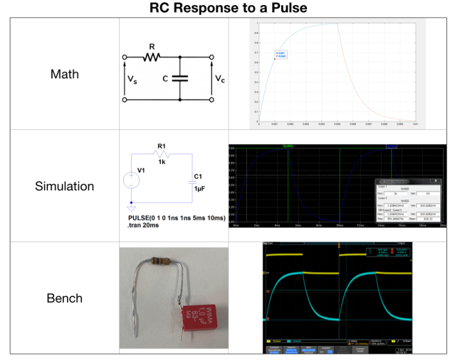
Now on to the simple RC example to a pulse response. First we will predict the output of the simple RC circuit for a pulse with 10ms period with 50% duty cycle and then we will verify it using LTspice simulation as well as on bench.
Same differential equation govern the behavior of this circuit except now source is a step DC voltage:

Vs=step voltage DC source
The solution for this differential equation is given below and derivation is in appendix below if you interested in math:
Vc = Vc – Vc*exp(t/RC) ———[1]
The intuition behind is simple as capacitor voltage cannot change instantaneously or in zero time because that would require infinite amount of current (i = C*dv/dt), so at the instant when step voltage is applied output voltage would be zero (assuming there is no initial voltage), but output slowly rise to its final value of Vs as capacitor charges. How slow or fast it charges is dictated by component value of resistor and capacitor, in particular their product RC called time constant. This is precisely predicted by the above equation and demonstrated by plotting this function in matlab below. As can be seen in table below, LTspice and calculation of RC time constant are exact match as they should be. I also did this experiment on the bench and results are very close to calculation/simulation:

The 2% discrepancy is most likely coming from component tolerances and oscilloscope cursor resolution.
LTspice file can be downloaded here.
Appendix

