
Kashif Javaid
Command covered: PWL .IC .tran
Capacitor stores energy in the form of an electric field. The energy is stored between its plates due to the separation of charge.
Inductor stores energy in the form of a magnetic field. The energy is stored in the magnetic field generated by the current flowing through the coil.
Now capacitors and inductors are considered dual to each other because what capacitor does to voltage is what inductor does to current. In other words in all the fundamental equations, voltage can be swapped to current or vice versa. See table below and pay close attention to Voltage (V) and Current (I) variables between two components.
| Capacitor | Inductor | |
| Physical Mechanism | Electric field | Magnetic field |
| Parameter | Voltage/Charge | Magnetic field lines/Current |
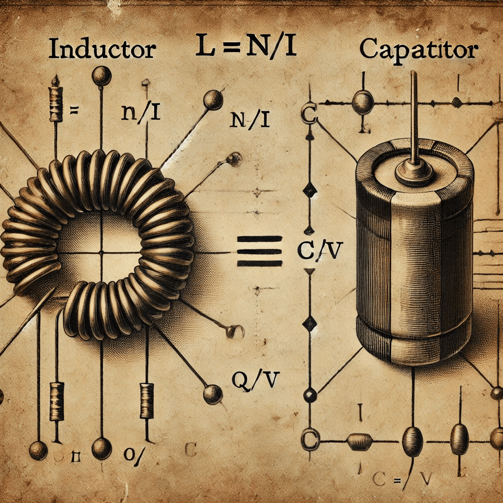
| Definition | C = Q / V | L = N / I |
| IV equation | I = C dV/dt | V = L dI/dt |
| IV equation | V = 1/C∫ I dt | I = 1/L ∫ V dt |
| Energy | E = 1/2 CV2 | E = 1/2 LI2 |
| AC Impedance | ZC = 1 / jwC | ZL = jwL |
| Series combination | 1/C = 1/C1 + 1/C2 … 1/CN | L = L1 + L2 … LN |
| Parallel combination | C = C1 + C2 … CN | 1/L = 1/L1 + 1/L2 … 1/LN |
| DC/low frequency | Open | Short |
| AC high frequencies | Short | Open |
Per component definition, Inductance is about the number of rings of magnetic-field lines (N) enclosing a wire per amp of the current, it is not about the absolute value of the magnetic-field density at any one point. Capacitance is always between two conductors and measure their capacity to store charge at the cost of voltage between them.

In a DC circuit, a fully charged capacitor behaves like an open circuit because it stops allowing current to flow once the voltage stabilizes, whereas in an inductor behaves like a short circuit once a steady current is established, as it opposes changes in current but not a constant current. After all inductor is piece of wire and wrapped up in a coil and capacitor consist of two metal plates physically separated by some distance.
Now this background out of the way, let’s take a look at basic fundamental circuits to illustrate duality concept further.

In Figure 1, capacitor C1 is driven by a PWL (PieceWise Linear) constant current source, as shown in blue in Figure 3. The resulting response is a voltage increase linearly from 0 to 10 µs. From 10 µs to 20 µs, the capacitor holds its voltage steady at 100 mV, and from 20 µs to 30 µs, the voltage decreases linearly. The mathematical explanation for this behavior is as follows:
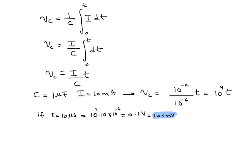


Figure 3: Top plots shows capacitor behavior and Bottom plots shows inductor behavior.
Note, inductor waveform looks identical but V and I are swapped as shown in figure 3 red and cyan traces.
Now let’s look at transient response of RC and RL circuit.
In RC and RL network shown in figure 4 below, time constant is setup as RC = 1ms both of these circuits. Output voltage vC = 1 – exp(-1000*t) and output current iL = 1 – exp(-1000*t)

Here is the output response, both RC and RL waveform looks identical but in RC circuit we are measuring the voltage at C1 and in RL circuit we are measuring current through L1 but notice that shape is exactly is the same because we kept the time constant exactly the same. What’s happening to the voltage in capacitor is the same as what’s happening to the current in inductor; they both exponentially goes to their final values.

Figure 6: Top plot show RC behavior and Bottom plot shows RL behavior
What’s happening to the voltage in capacitor is the same as what’s happening to the current in inductor; they both exponentially goes to their final values.
Now let’s look at what happen if we drive these circuits with ac input in figure 7 and figure 8 and get their filter response. RC is a simple passive low pass filter—considering duality—RL then is a simple passive high pass filter. With time constant of 1ms and using formula F_3dB = 1/(2*pi*time_constant) for cut-off or corner -3dB frequency is around 159Hz.

Frequency response of RC filter network can be described as below:
Intuitively, in an RC circuit, at low frequencies, the capacitor acts almost like an open circuit because its impedance, ZC=1 /jωC, is high. As a result, the output voltage is nearly equal to the input. However, at higher frequencies, the capacitor behaves more like a short circuit, allowing the signal become smaller and smaller, as shown in the plot (green) below. This is why the RC circuit functions as a low-pass filter (LPF), allowing low-frequency signals to pass while attenuating high frequencies.
In contrast, in an RL circuit, due to the principle of duality, the opposite behavior occurs, making it a high-pass filter (HPF). At low frequencies, the inductor acts almost like a short circuit because its impedance, ZL=jωL, is low, causing the signal amplitude to be attenuated. At higher frequencies, the inductor behaves like an open circuit, allowing the output to be close to the input as shown in the plot (blue) below:

Feel free to play with these simulations to get better understanding of duality nature of L and C components. LTspice files are downloadable in the below link:
